Pneuquad (Pneumatic Quadruped Robot)
Why did we build it?
Skip to the Results section to see the performance.
Building upon the experience gained in Robocon, having to submit our final project and with the thirst to try something new, me and my colleagues from Robocon decided to work on a 4-legged robot. Around that time (2017), Boston Dynamics released videos of the BigDog and SpotMini which were under development for a long time.
We observed that most of these robots used electric and hydraulic actuators, with good reason. With the eagerness to try something new (not necessarily better), we used pneumatic actuators (we also had a lot of experience using these). As usual, this was unknown territory; so we began by making prototypes, using the spare pneumatic cylinders and fittings we had, pieces of aluminum and steel lying around and plastic coke bottles filled with compressed air. The first prototype was simply a 2 legged one, with wheels in the front (as shown on the right).

First 4-legged prototype
Drawing upon the successful walk of the 2-legged prototype, we built a 4-legged prototype and tested it. Not unsurprisingly, the pneumatic actuators were insufficient to move the robot. (Shown on right).
We understood that we had to size the pneumatic actuators correctly (or in excess of the payload) and have optimal kinematics for the legs to maximize the effective force from those pneumatic actuators.

Design methodology
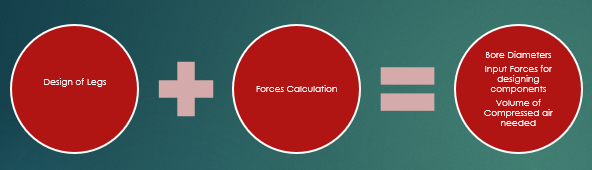
After the testing of the first 4-legged prototype, we had enough intuition to develop a formal understanding of the physics of making a quadruped robot walk. This meant doing the following :
-
Leg kinematics
-
Force estimation
-
Design of Physical Components
Leg Kinematics

I am not going to lie, I didn't exactly apply inverse kinematics here. This is exactly what I did:
- We knew the approximate size of the robot we were making, and therefore, we knew the approximate trajectory that the foot of the robot would make in the most common gaits (like walking).
- Drawing on this, I started off with initial sizes of the 2 linkages (upper & lower leg) and based on what's available in the market, I started off with pneumatic cylinders with a certain length (and stroke length). Since we were only interested in the geometry, and the movement of the linkages (kinematics), I utilized the Blocks functionality provided by Solidworks and ended up with a diagram (as shown above).
- I then optimized all of the above dimensions (leg lengths, cylinder lengths and stroke lengths) iteratively to get the desired foot trajectory.
Force Estimation / Pneumatic Cylinder Sizing
Now that we had the geometry and kinematics of the legs, the next step was to provide enough force to actually make the legs walk. This was done in 6 steps :
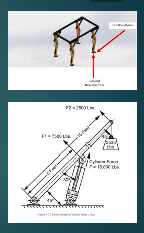
- Analyze the maximum force the legs were subjected to over one complete trajectory of the foot. The ground reaction force would have a vertical and horizontal component which are proportional to the robot's overall weight (including payload).
- This payload included :
- The overall frame.
- The compressed air tank we would mount to supply power to the actuators.
- A robotic arm we were planning to mount.
- Electronics (Solenoid valves, boards, batteries, etc)
- This payload included :
- The force that the pneumatic cylinder would need to exert was computed using a crane model where the closer the cylinder is bolted to the force (See Image on right, the cylinder is bolted 15 feet away from the point at which the force acts), the lesser is the force exerted.
- Given our preset constraint i.e, the geometry of the leg, we we came up with the force needed to be exerted by a single pneumatic cylinder.
- Further, we had 2 cylinders per leg, and depending on the orientation of each cylinder both cylinders would work together exerting varying amounts of forces during the motion of the foot.
- We made a simplifying assumption here; the 2 cylinders are almost collinear and can be treated as if they were attached in series and pushing against that leg together.
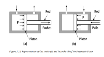
- Further, the double-acting pneumatic cylinders we used would not exert equal amounts of forces in both directions (as illustrated on the right). During the instroke, the compressed air would only act on an area made up of the bore diameter (the inner diameter of the cylinder) minus the piston's diameter.
- For this reason, we decided to flip the rear legs 180 degrees which allows the outstroke force to be used when the legs are actually pushing against the ground. The instroke forces would only be used for lifting the foot up for the next cycle, where the force required is almost insignificant in comparison.
- Now that we had the maximum force required per pneumatic cylinder, we selected a bore diameter for the cylinders that would provide a force in excess of this maximum force.
Design of Physical Components (Using Structural Analysis)
Now that we know the forces acting on different components during the robot's motion, we could design the linkages. It was dine in 3 stages :
- Made initial design.
- Subject the calculated forces (Forces acting at foot => Lower Leg => Upper Leg => Chassis) using Free Body Diagrams.
- Iteratively adjust the thickness and other dimensions that improve the factor of Safety of initially designed components.

I used Solidworks Simulation to do this. This module uses FEA to estimate the stresses and strains on every "mesh". All I had to do was specify how much force was acting on a specific region of the component, and the various fixtures of the component. For eg: the upper leg was bolted to the chassis, the lower leg and the pneumatic cylinder actuating it.
The compressed air cylinder was subject to a maximum pressure of 6 bars on its inner walls. I used the Flow Simulation module of Solidworks to check whether everything held up given these conditions.
Results
It walked, as you can see below! Further, here's our slightly longer marketing video.
Acknowledgements
Shoutout to my colleagues!
- Muqeeth and Ausaf took the initiative for this project, put together the team and dragged me into it while I was the Captain for Robocon 2018! They did much of the initial prototyping as they were understanding of my responsibilities as Captain for Robocon, with me only getting substantially involved in it during the design stages (I was mostly only brainstorming during the prototyping stage).
- Abdul Aziz did all the electronics for this project. Couldn't have done it without him!
- Faisal managed the project, keeping us all organized with our budget and time, coordinating with the college, composing the thesis and various reports and since we took part in some competitions with this project, he managed all the logistics. It was during this time I realized that having an effective project manager like him goes a long way in keeping things smooth!